Product Overview
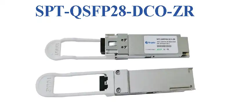
The SPT-QSFP28-DCO-ZR is a QSFP28 packaged 100Gb/s Digital Coherent Optics (DCO) transceiver module. This module supports DP-DQPSK modulation format, C-band tunable laser, 80km transmission distance, uses LC interface, and supports hot-pluggable. Suitable for long-haul transmission, metro networks, data center interconnects and other application scenarios.
Features
- QSFP28 Package: Complies with QSFP28 Multi-Source Agreement standard
- 100Gb/s Data Rate: Supports 4×27.95GBd symbol rate
- DP-DQPSK Modulation Format: Dual-Polarization Differential Quadrature Phase Shift Keying
- C-band Tunable: Supports 100GHz and 50GHz grid
- 80km Transmission Distance: Meets long-haul transmission needs
- LC Interface: Standard LC fiber optic connector
- Hot-Pluggable: Supports live plugging and unplugging
- Digital Diagnostic Monitoring: Supports DDM function
- Commercial Temperature Range: 0°C to 70°C
Absolute Maximum Ratings
| Parameter | Symbol | Min | Max | Unit |
|---|
| Supply Voltage | Vcc | -0.3 | 4.0 | V |
| Operating Temperature | TOP | 0 | 70 | °C |
| Storage Temperature | TST | -40 | 85 | °C |
| Relative Humidity | RH | 0 | 85 | % |
Recommended Operating Conditions
| Parameter | Symbol | Min | Typ | Max | Unit |
|---|
| Supply Voltage | Vcc | 3.0 | 3.3 | 3.6 | V |
| Operating Temperature (Commercial) | TOP | 0 | 25 | 70 | °C |
Electrical Characteristics
| Parameter | Symbol | Min | Typ | Max | Unit |
|---|
| Supply Current | Icc | - | - | 1500 | mA |
| Maximum Power Dissipation | Pmax | - | - | 5.0 | W |
| Input Differential Impedance | Rin | 90 | 100 | 110 | Ω |
| Single-Ended Data Input Swing | VinPP | 200 | - | 1200 | mVp-p |
| Single-Ended Data Output Swing | VoutPP | 300 | - | 1000 | mV |
| Data Output Rise Time | tr | - | - | 1300 | ps |
| Data Output Fall Time | tf | - | - | 1300 | ps |
Optical Parameters
General Parameters
| Parameter | Conditions | Symbol | Min | Typ | Max | Unit |
|---|
| Symbol Rate | - | Rbaud | - | 27.95 | - | GBd |
| Modulation Format | - | - | DP-DQPSK | - | - | - |
| Channel Frequency Range (100GHz Grid) | - | λC | 191.40 | 193.70 | 196.10 | THz |
| Channel Frequency Range (50GHz Grid) | - | λC | 191.35 | 193.70 | 196.10 | THz |
| Channel Spacing (100GHz Grid) | - | Δλ | - | 100 | - | GHz |
| Channel Spacing (50GHz Grid) | - | Δλ | - | 50 | - | GHz |
| Frequency Accuracy | - | ΔλC | -1.8 | - | 1.8 | GHz |
| Laser Intrinsic Linewidth | Calculated based on FM noise power spectral density (PSD) measurement | LW | - | - | 500 | kHz |
| Side-Mode Suppression Ratio | No modulation | SMSR | 40 | - | - | dB |
| Relative Intensity Noise | Peak over 0.2GHz < f < 10GHz | RIN | - | - | -140 | dB/Hz |
Transmitter Parameters
| Parameter | Conditions | Symbol | Min | Typ | Max | Unit |
|---|
| TX Output Power | - | PTXout | -8 | - | -4 | dBm |
| TX Output Power (Monitor) | - | PTXmon | -10 | - | -2 | dBm |
| TX Output Power Monitor Accuracy | TX optical power monitor reading relative to actual TX output power | ΔPTXmon | -1.5 | - | 1.5 | dB |
| TX Output Power During Tuning or When TX Disabled | - | PTXdark | - | - | -35 | dBm |
| TX Spectral Excursion | ITU-T G.698.2 Section 7.2.3 | - | -15 | - | 15 | GHz |
| TX Output Power Imbalance Between X and Y | - | ΔPTX/Y | - | - | 1.5 | dB |
| TX X and Y Polarization Skew | - | - | - | - | 6.0 | ps |
Receiver Parameters
| Parameter | Conditions | Symbol | Min | Typ | Max | Unit |
|---|
| RX Input Power | - | PRXin | -22 | - | -9 | dBm |
| RX Input Power (Monitor) | - | PRXmon | -24 | - | -7 | dBm |
| RX Input Power Monitor Accuracy | RX optical power monitor reading relative to actual RX input power | ΔPRXmon | -1.5 | - | 1.5 | dB |
| RX Reflectance | - | - | - | - | -12 | dB |
Optical Signal-to-Noise Ratio (OSNR) Tolerance
| Parameter | Conditions | Symbol | Min | Typ | Max | Unit |
|---|
| OSNR Tolerance (100G DP-DQPSK) | BER = 2.4E-2 (SD-FEC threshold) | - | - | - | 14 | dB |
Timing Specifications
Initialization and Control Timing
| Parameter | Conditions | Symbol | Min | Typ | Max | Unit |
|---|
| Serial Bus Hardware Ready Time | Time from power on until the module responds to data transmission over the two-wire serial bus | - | - | - | 2 | s |
| Monitor Data Ready Time | Time from power on to Data_Not_Ready Byte 2 bit 0 cleared to 0 and IntL output pulled low | - | - | - | 2 | s |
| Reset Assert Time | Time from a rising edge on the ResetL input until the module is fully functional | - | - | - | 120 | s |
| LPMode/TxDis Mode Change Time | Time to change between LPMode and TxDis modes of the dual-mode signal LPMode/TxDis | - | - | - | 100 | ms |
| LPMode Assert Time | Time from when the host releases LPMode to high until module power consumption reaches PowerClass1 | - | - | - | 100 | ms |
| LPMode Deassert Time | Time from when the host pulls LPMode low until the module is fully functional | - | - | - | 120 | s |
| IntL/RxLOSL Mode Change Time | Time to change between IntL and RxLOSL modes of the dual-mode signal IntL/RxLOSL | - | - | - | 100 | ms |
| IntL Assert Time | Time from occurrence of condition triggering an interrupt until IntL is low | - | - | - | 200 | ms |
| IntL Deassert Time | Time from clear on read operation of associated flag until module releases IntL to high. This includes the time to clear RxLOS, TxFault and other flag bits | - | - | - | 500 | μs |
| RxLOSL Assert Time | Time from optical loss of signal to RxLOSL signal pulled low by the module | - | - | - | 1 | ms |
| RxLOSL Deassert Time | Time from optical signal above the LOS deassert threshold to when the module releases the RxLOSL signal to high | - | - | - | 3 | ms |
| TxFault Assert Time | Time from Tx Fault state to Tx Fault bit set to 1 and IntL pulled low by the module | - | - | - | 200 | ms |
| Flag Assert Time | Time from condition triggering flag to associated flag bit set to 1 and IntL pulled low by the module | - | - | - | 200 | ms |
| Mask Assert Time | Time from mask bit set to 1 until the module is prevented from pulling IntL low when the associated flag is set high | - | - | - | 100 | ms |
| Mask Deassert Time | Time from mask bit cleared to 0 until module is enabled to pull IntL low when the associated flag is set high | - | - | - | 100 | ms |
Squelch and Disable I/O Timing
| Parameter | Conditions | Symbol | Min | Typ | Max | Unit |
|---|
| RX Squelch Assert Time | Time from loss of RX input signal until the squelched output condition is reached | - | - | - | 15 | ms |
| RX Squelch Deassert Time | Time from resumption of RX input signals until normal RX output condition is reached | - | - | - | 15 | ms |
| TX Squelch Assert Time | Time from loss of TX input signal until the squelched output condition is reached | - | - | - | 400 | ms |
| TX Squelch Deassert Time | Time from resumption of TX input signals until normal TX output condition is reached | - | - | - | 10 | s |
| TX Disable Assert Time | Time from TX Disable bit set to 1 until optical output falls below 10% of nominal | - | - | - | 1 | ms |
Optical Timing
| Parameter | Conditions | Symbol | Min | Typ | Max | Unit |
|---|
| TX Turn On Time | Warm start | - | - | - | 10 | s |
| TX Turn On Time | Cold start | - | - | - | 120 | s |
| RX Acquisition Time | Warm start | - | - | - | 30 | ms |
| RX Acquisition Time | Cold start | - | - | - | 120 | s |
| TX/RX Channel Tuning | - | - | - | - | 30 | s |
Pin Definitions
Diagram of Host Board Connector Block Pin Numbers and Names
| Pin | Logic | Symbol | Name/Description | Ref. |
|---|
| 1 | - | GND | Ground | 1 |
| 2 | CML-I | Tx2n | Transmitter Inverted Data Input | - |
| 3 | CML-I | Tx2p | Transmitter Non-Inverted Data Output | - |
| 4 | - | GND | Ground | 1 |
| 5 | CML-I | Tx4n | Transmitter Inverted Data Output | - |
| 6 | CML-I | Tx4p | Transmitter Non-Inverted Data Output | - |
| 7 | - | GND | Ground | 1 |
| 8 | LVTTL-I | ModSelL | Module Select | - |
| 9 | LVTTL-I | ResetL | Module Reset | - |
| 10 | - | VccRx | +3.3V Power Supply Receiver | 2 |
| 11 | LVCMOS-I/O | SCL | 2-Wire Serial Interface Clock | - |
| 12 | LVCMOS-I/O | SDA | 2-Wire Serial Interface Data | - |
| 13 | - | GND | Ground | 1 |
| 14 | CML-O | Rx3p | Receiver Inverted Data Output | - |
| 15 | CML-O | Rx3n | Receiver Non-Inverted Data Output | - |
| 16 | - | GND | Ground | 1 |
| 17 | CML-O | Rx1p | Receiver Inverted Data Output | - |
| 18 | CML-O | Rx1n | Receiver Non-Inverted Data Output | - |
| 19 | - | GND | Ground | 1 |
| 20 | - | GND | Ground | 1 |
| 21 | CML-O | Rx2n | Receiver Inverted Data Output | - |
| 22 | CML-O | Rx2p | Receiver Non-Inverted Data Output | - |
| 23 | - | GND | Ground | 1 |
| 24 | CML-O | Rx4n | Receiver Inverted Data Output | - |
| 25 | CML-O | Rx4p | Receiver Non-Inverted Data Output | - |
| 26 | - | GND | Ground | 1 |
| 27 | LVTTL-O | ModPrsL | Module Present | - |
| 28 | LVTTL-O | IntL | Interrupt | - |
| 29 | - | VccTx | +3.3V Power Supply Transmitter | 2 |
| 30 | - | Vcc1 | +3.3V Power Supply | 2 |
| 31 | LVTTL-I | LPMode | Low Power Mode | - |
| 32 | - | GND | Ground | 1 |
| 33 | CML-I | Tx3p | Transmitter Inverted Data Output | - |
| 34 | CML-I | Tx3n | Transmitter Non-Inverted Data Output | - |
| 35 | - | GND | Ground | 1 |
| 36 | CML-I | Tx1p | Transmitter Inverted Data Output | - |
| 37 | CML-I | Tx1n | Transmitter Non-Inverted Data Output | - |
| 38 | - | GND | Ground | 1 |
Notes
- GND is the symbol for single and supply (power) common for QSFP modules. All are common within the QSFP module and all module voltages are referenced to this potential otherwise noted. Connect these directly to the host board signal common ground plane. Laser output disabled on TDIS>2.0V or open, enabled on TDIS<0.8V.
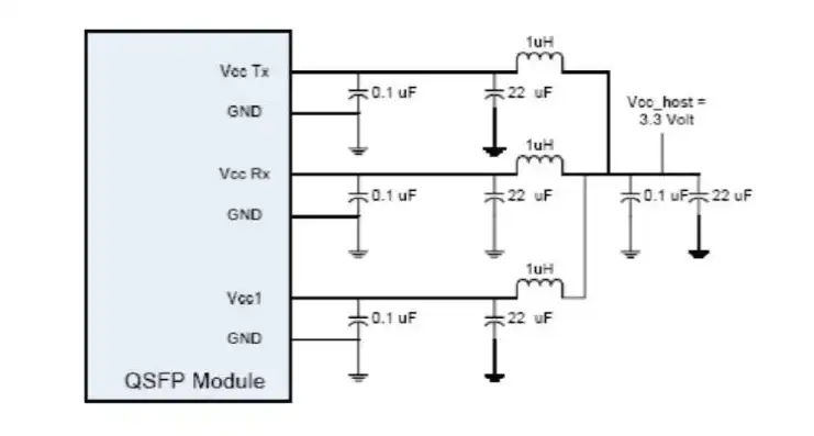
- VccRx, Vcc1 and VccTx are the receiver and transmitter power suppliers and shall be applied concurrently. Recommended host board power supply filtering is shown below. VccRx, Vcc1 and VccTx may be internally connected within the QSFP transceiver module in any combination. The connector pins are each rated for maximum current of 500mA.
Recommended Circuit & Mechanical Dimensions
Recommended Circuit
Please refer to the recommended circuit diagram
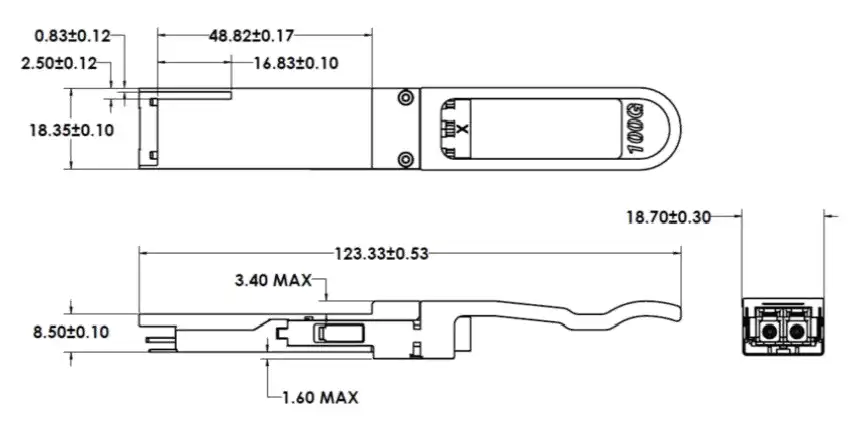
Mechanical Drawing
Please refer to the mechanical dimensions drawing
Ordering Information
| Part Number | Product Description |
|---|
| SPT-QSFP28-DCO-ZR | QSFP28 100Gb/s Digital Coherent Optics Transceiver, Duplex LC, Hot-Pluggable, Fixed Grid C-band Tunable, SMF 80km, Commercial Temperature |
Contact Us
Email: info@sopto.com.cn
Web: http://www.sopto.com.cn
Note: If you need more customized services, please contact us.