The Complete Guide to Optical Transceivers
Optical transceivers are the heart of fiber optic networks, performing vital electro-optical conversions. This guide covers working principles, key performance metrics, classifications, naming conventions, and safe handling procedures.
1. Working Principles & Structure
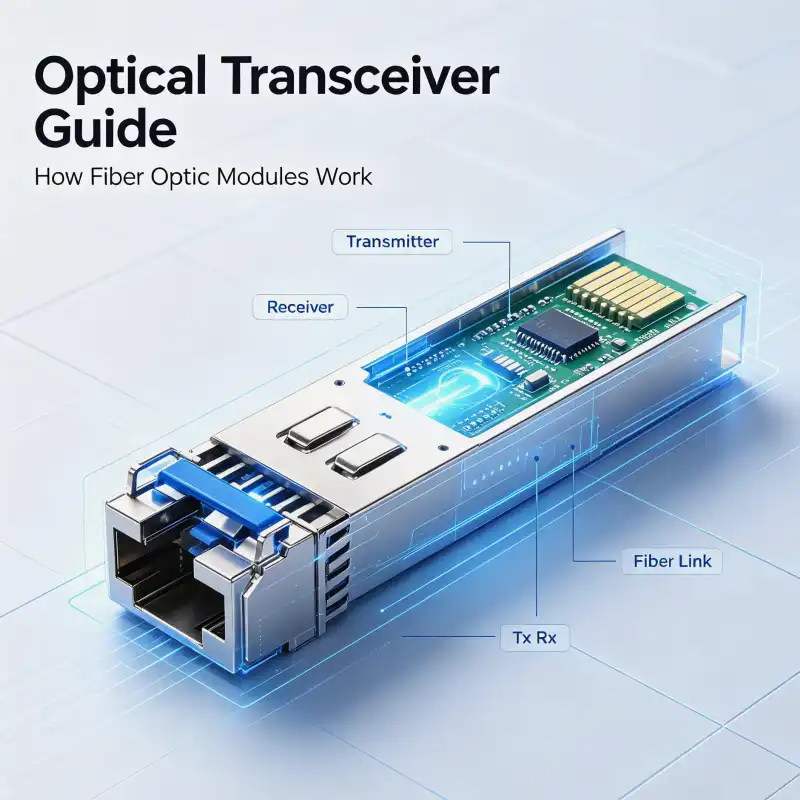
Operating at the Physical Layer of the OSI model, an optical transceiver consists of a laser/LED (Tx), a photodiode (Rx), driver ICs, and optical interfaces. Its core function is bidirectional conversion between electrical and optical signals.
Workflow: The transmitter converts electrical bits into a modulated light signal. This signal travels via fiber to the receiver, where a photodiode converts it back into an electrical signal for the host device.
A typical SFP module includes: a dust cap, a bail latch (color-coded by wavelength), a label, an electrical edge connector, Rx/Tx optical ports, and a metal shell.
2. Key Performance Metrics
Transmitter Side
- Average Launch Power: Output power in dBm. Higher power generally allows for longer reach.
- Extinction Ratio: The ratio (in dB) of optical power in a "1" bit to a "0" bit (typically 8.2~10dB), indicating signal distinction capability.
- Center Wavelength: The peak wavelength (e.g., 850nm for MM, 1310/1550nm for SM), chosen based on the fiber's low-loss windows.
Receiver Side
- Receiver Sensitivity: The minimum average optical power required to achieve a BER of 1E-12. A more negative value indicates higher sensitivity.
- Overload Power: The maximum average optical power the receiver can tolerate before saturation and damage occur.
- Receiver Power Range: The operational window between Sensitivity and Overload. Actual received power must stay within this range.
Composite Metrics
- Data Rate: Ranging from 125Mbps (FE) to 400Gbps and beyond.
- Link Distance: Primarily limited by fiber attenuation: Distance ≈ (Tx Power - Rx Sensitivity) / Fiber Attenuation (dB/km).
3. Classification & Naming Conventions
Common Classifications
- By Rate: FE, GE, 10GE, 25GE, 40GE, 100GE, 400GE.
- By Form Factor: SFP/eSFP, SFP+, SFP28, QSFP+, QSFP28, QSFP-DD, CXP, CFP.
- By Mode: Single-mode (1310/1550nm, long-haul) vs. Multi-mode (850nm, short-haul, cost-effective).
- By Wavelength: Grey (single λ) vs. Color (CWDM/DWDM, multiplexed, saves fiber for long-haul backbones).
Generic Naming Rule (A-B-C-D-E-F)
- A: Form Factor (e.g., QSFP28)
- B: Data Rate (e.g., 100GE)
- C: Distance Type (SX/LX/LH)
- D: Distance (km)
- E: Mode (SM/MM)
- F: Wavelength (nm)
Example: SFP-10G-LR-10-SM-1310 = 10G SFP+, Long-reach 10km, Single-mode, 1310nm.
4. Handling & Failure Prevention
Improper handling is the leading cause of failure. Focus on ESD and physical protection.
- ESD Protection: Always keep modules in anti-static packaging until use. Wear wrist straps and gloves. Ensure equipment grounding.
- Physical Care: Handle with care; avoid drops. Use only hands on the bail latch—no metal tools. Clean ports only with specialized swabs. Keep dust caps on when not in use.
- Power Control: When using long-reach modules on short fibers, calculate power. Add attenuators if necessary to keep received power below the overload threshold to prevent damage.
Pro Tip: Correct selection and handling significantly extend module lifespan and network stability. SOPTO offers a full portfolio of high-performance transceivers and technical support.
Explore SOPTO Optical Solutions
From 1.25G to 400G, covering SFP, QSFP, CWDM/DWDM. ISO9001 certified, 100% tested for reliability.