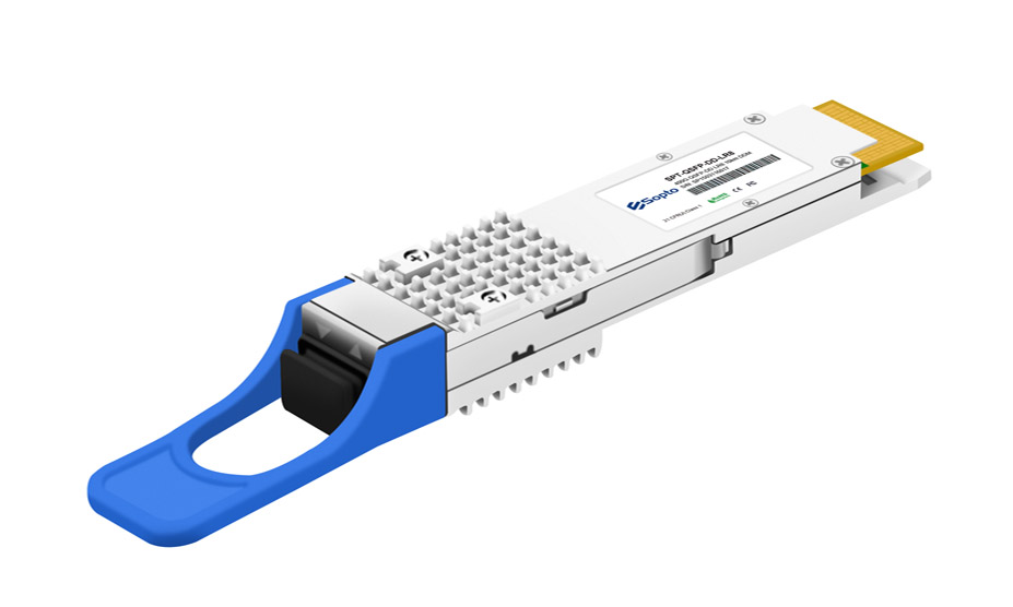
SPT-QD04G-SR4 400G QSFP-DD SR4 Optical Transceiver Module
Based on the official SOPTO product specification (SPT-QD04G-SR4 Datasheet)
1. Product Overview
The SPT-QD04G-SR4 is a 400Gb/s QSFP-DD SR4 optical transceiver module from SOPTO, designed for short-reach optical communication scenarios up to 100m. On the transmit side, the module converts 8-channel 50Gb/s PAM4 electrical signals into 4-channel parallel optical signals (100Gb/s per channel), for an aggregate data rate of 400Gb/s. On the receive side, it performs the reverse operation, converting 4-channel 100Gb/s parallel optical signals back into 8-channel 50Gb/s PAM4 electrical signals, also at an aggregate rate of 400Gb/s.
The module uses an MTP/MPO-12 connector and operates at 850nm wavelength. Paired with OM4 multimode fiber (MMF), it supports link distances up to 100m. The product complies with the QSFP-DD MSA Rev 6.2 hardware specification and CMIS 4.0 software interface specification, and is compatible with the IEEE 802.3db 400GBASE-SR4 standard. It is primarily used in 400G Ethernet, data center interconnect, and enterprise networking applications.
400Gb/s
Aggregate Rate
100m
OM4 Link Distance
9W
Max Power Consumption
850nm
Operating Wavelength
2. Key Features
- QSFP-DD MSA Compliant: Compatible with QSFP-DD / QSFP-DD800 / QSFP112 Rev 6.2 hardware specifications, ensuring physical interoperability with mainstream network equipment.
- CMIS 4.0 Interface Protocol: Follows the Common Management Interface Specification 4.0, supporting standardized module management and digital diagnostic functions.
- 4-Way Parallel Optical Lanes: Employs a 4-lane parallel optical design, each at 100Gb/s, achieving high-density transmission via PAM4 modulation format.
- IEEE 802.3db Compatible: Meets the 400GBASE-SR4 specification, ensuring interoperability with network equipment conforming to this standard.
- 400GAUI-8 Electrical Interface: The electrical side uses an 8×53.125Gb/s interface (400GAUI-8) to interface with host-side high-speed electrical signals.
- Low Power Design: Maximum power consumption of 9W with a single 3.3V supply, representing a low level for the 400G speed class.
- Wide Temperature Range: Case operating temperature of 0°C to +70°C, covering typical commercial temperature ranges.
- RoHS 2.0 Compliant: Meets the RoHS 2.0 environmental standard, satisfying green manufacturing requirements.
3. Technical Specifications
3.1 Absolute Maximum Ratings
The following parameters represent the device's maximum stress limits. Exceeding them may cause permanent damage. These are not normal operating conditions.
| Parameter | Symbol | Min | Max | Unit |
|---|---|---|---|---|
| Storage temperature range | TSTG | -40 | +85 | °C |
| Supply voltage | VCC | 0.5 | 3.6 | V |
| Relative humidity | RH | 10% ~ 90% (non-condensing) | — | |
3.2 Operating Conditions
| Parameter | Symbol | Min | Max | Unit |
|---|---|---|---|---|
| Case temperature (operating) | TCASE | 0 | 70 | °C |
| Supply voltage | VCC | 3.135 | 3.465 | V |
| Power consumption | PDISS | — | 9 | W |
| Pre-FEC bit error ratio | — | — | 2.4×10⁻⁴ | — |
| OM3 fiber link distance | — | 0.5 | 60 | m |
| OM4 fiber link distance | — | 0.5 | 100 | m |
Note on FEC: The module requires the host to enable FEC (Forward Error Correction) to support fiber transmission up to 100m. The Pre-FEC bit error ratio upper limit is 2.4×10⁻⁴. Within this range, FEC error correction ensures reliable, loss-free transmission.
3.3 Transmitter Optical Specifications
| Parameter | Min | Typ | Max | Unit |
|---|---|---|---|---|
| Signal rate per channel | 53.125 ±100ppm | — | GBd | |
| Channel wavelength range | — | 850 | — | nm |
| RMS spectral width | — | — | 0.6 | nm |
| Modulation format | PAM4 | — | ||
| Average optical power per channel | -4.6 | — | 4 | dBm |
| OMA outer (when TDECQ ≤ 1.8dB) | -2.6 | — | 3.5 | dBm |
| OMA outer (when 1.8 < TDECQ ≤ 4.4dB) | -4.4+TDECQ | — | 3.5 | dBm |
| TDECQ (per channel) | — | — | 4.4 | dB |
| Extinction ratio | 2.5 | — | — | dB |
| Transmitter transition time (per channel) | — | — | 17 | ps |
| Average transmit power in TX off state | — | — | -30 | dBm |
| Relative intensity noise (OMA) | — | — | -131 | dB/Hz |
| Optical return loss tolerance | — | — | 12 | dB |
3.4 Receiver Optical Specifications
| Parameter | Min | Typ | Max | Unit |
|---|---|---|---|---|
| Signal rate per channel | 53.125 ±100ppm | — | GBd | |
| Channel wavelength range | — | 850 | — | nm |
| Modulation format | PAM4 | — | ||
| Damage threshold | 5 | — | — | dBm |
| Average received optical power per channel | -6.4 | — | 4 | dBm |
| Receiver sensitivity (OMA outer, TECQ ≤ 1.8dB) | — | — | -4.6 | dBm |
| Receiver sensitivity (OMA outer, 1.8 < TECQ ≤ 4.4dB) | — | — | -6.4+TECQ | dBm |
| Receiver reflectance | — | — | -12 | dB |
| Stressed receiver sensitivity (OMA outer) | — | — | -2 | dBm |
3.5 Loss of Signal (LOS) Thresholds
| Parameter | Min | Typ | Max | Unit |
|---|---|---|---|---|
| LOS assert threshold | -15.0 | — | — | dBm |
| LOS deassert threshold | — | — | -8.9 | dBm |
| LOS hysteresis | — | 1.5 | — | dB |
The LOS (Loss of Signal) mechanism detects whether the received optical signal has been lost. A LOS alarm is triggered when the received power falls below -15.0 dBm, and is deasserted when the power recovers above -8.9 dBm. The 1.5 dB hysteresis effectively prevents frequent toggling near the threshold.
4. Digital Diagnostic Monitoring (DDM)
The SPT-QD04G-SR4 supports Digital Diagnostic Monitoring, allowing real-time reading of internal module status parameters via the CMIS interface. This enables operators to perform link monitoring and fault diagnostics. The accuracy specifications for each monitored parameter are as follows:
| Monitored Parameter | Unit | Accuracy |
|---|---|---|
| Temperature monitoring | °C | ±3 |
| Supply voltage monitoring | % | ±5 |
| Bias current (I_bias) monitoring | % | ±10 |
| Received optical power (Rx) monitoring | dB | ±3.0 |
| Transmitted optical power (Tx) monitoring | dB | ±3.0 |
5. Operating Principle
The core operating principle of the SPT-QD04G-SR4 is electrical-to-optical / optical-to-electrical conversion with lane multiplexing. The module contains two independent data paths for transmission and reception:
Transmit direction: The host inputs 8-channel 50Gb/s PAM4 electrical signals via the 400GAUI-8 electrical interface. The internal driver IC processes these electrical signals and drives a VCSEL laser array (850nm), combining the 8 electrical channels into 4 optical channels. Each optical channel carries 100Gb/s of data, for an aggregate of 400Gb/s. The optical signals are coupled into multimode fiber through the MTP/MPO-12 connector.
Receive direction: The 4-channel 100Gb/s parallel optical signals from the fiber enter the module through the MTP/MPO-12 connector and are converted into electrical signals by a PIN photodiode array. The receiver IC restores the 4-channel 100Gb/s optical signals into 8-channel 50Gb/s PAM4 electrical signals, which are output to the host via the 400GAUI-8 interface, at an aggregate rate of 400Gb/s.
The following table shows the module's data lane assignment:
| Direction | Electrical Side (Host) | Optical Side (Fiber) | Wavelength |
|---|---|---|---|
| Tx (Transmit) | 8 × 50Gb/s PAM4 | 4 × 100Gb/s | 850nm |
| Rx (Receive) | 8 × 50Gb/s PAM4 | 4 × 100Gb/s | 850nm |
The module employs PAM4 (4-level Pulse Amplitude Modulation) technology, where each symbol carries 2 bits of information. Compared to traditional NRZ modulation, this doubles the per-channel data rate and is a key enabling technology for 400G short-reach transmission. Additionally, the module requires host-side FEC support to maintain link reliability at high data rates.
6. Applications
The SPT-QD04G-SR4 is designed for short-reach, high-bandwidth optical interconnect scenarios. Typical applications include:
400G Ethernet
400G link interconnection between data center switches, meeting short-reach port requirements of the 400GBASE-SR4 standard.
Data Center Interconnect
High-bandwidth, low-latency interconnection within a single data center or between data centers in the same metro area, suitable for intra-room fiber cabling up to 100m.
Enterprise Networking
High-rate expansion of enterprise core network backbone links, supporting large-scale data transfer and storage network access.
Note that this module is a short-reach multimode fiber solution, and the supported link distance depends on the fiber type: up to 60m with OM3 multimode fiber and up to 100m with OM4 multimode fiber. For longer-distance transmission, single-mode fiber solutions (such as LR4/FR4 models) should be considered.
7. Electrical and Mechanical Interface
7.1 Electrical Interface
The module connects to the host board via a QSFP-DD edge finger connector and includes the following key signal groups:
- High-speed signals: 8 differential lane pairs, each at 26.5625 GBd signal rate, for 400GAUI-8 data transmit/receive. The receiver differential peak-to-peak voltage is 900mV, with an eye diagram height of no less than 24mV.
- Low-speed control signals: I²C-compatible SCL/SDA bus for CMIS communication; LPMode/TxDis, Reset, ModSelL for module control; IntL/RxLOS for interrupt and loss-of-signal indication; ModPrsL for module presence detection.
- Power supply: Single +3.3V power supply, operating voltage range 3.135V to 3.465V.
7.2 Optical Interface
The module uses an MTP/MPO-12 connector (male, located on the module front panel), which enables single-plug mating of 4 transmit and 4 receive optical lanes. The connector uses a 12-fiber ribbon, with 4 fibers for transmit, 4 for receive, and 4 unused positions (crossed arrangement). When in use, ensure the fiber patch cable is an MPO/MTP-12 multimode OM3/OM4 fiber to match the module's optical specifications.
7.3 Mechanical Specifications
The module follows the QSFP-DD MSA standard mechanical dimensions, with a form factor identical to a standard QSFP-DD module. It can be installed in the panel slots of network equipment such as switches and routers that support QSFP-DD ports. The case operating temperature range is 0°C to +70°C (commercial temperature grade), and the storage temperature range is -40°C to +85°C.
8. Ordering Information
| Part Number | Product Description |
|---|---|
| SPT-QD04G-SR4 | QSFP-DD optical transceiver module, 850nm, 400G SR4, 100m/OM4, MPO/MTP interface, with DDM, commercial temperature |
For customization services, please contact SOPTO via the following:
- Email: info@sopto.com.cn
- Website: www.sopto.com.cn
9. Glossary
| Abbreviation | Full Name | Description |
|---|---|---|
| QSFP-DD | Quad Small Form-factor Pluggable - Double Density | Double-density quad small form-factor pluggable package, supports 8 high-speed lane pairs |
| PAM4 | 4-level Pulse Amplitude Modulation | 4-level pulse amplitude modulation, 2 bits per symbol |
| CMIS | Common Management Interface Specification | Common management interface specification, used for module management communication |
| DDM | Digital Diagnostic Monitoring | Digital diagnostic monitoring, real-time monitoring of module status parameters |
| FEC | Forward Error Correction | Forward error correction, corrects transmission bit errors at the receiver |
| MPO/MTP | Multi-fiber Push-On / MTP | Multi-fiber push-pull optical connector |
| OM3/OM4 | Optical Multimode | Multimode fiber grades, OM4 outperforms OM3 |
| VCSEL | Vertical-Cavity Surface-Emitting Laser | Vertical-cavity surface-emitting laser, a common light source for short-reach optical communication |
| TDECQ | Transmitter and Dispersion Eye Closure for PAM4 | PAM4 transmitter dispersion eye closure metric |
| LOS | Loss of Signal | Loss of signal detection |