Product Overview
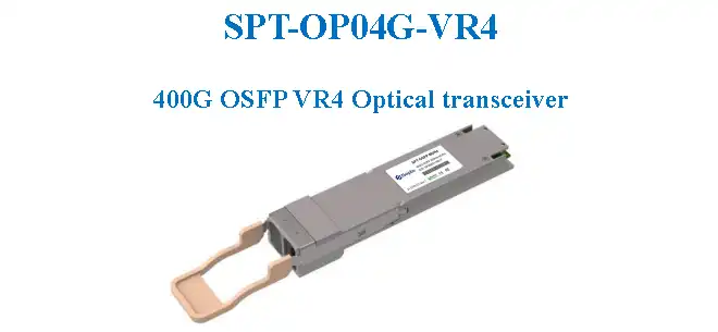
The SPT-OP04G-VR4 is an OSFP400 packaged 400G-VR4 optical transceiver module that supports a 400Gbps data transmission rate, with a maximum transmission distance of 50m over OM4/OM5 multi-mode fiber and 30m over OM3 multi-mode fiber. The module converts 4 channels of 100Gb/s (PAM4) electrical input data into 4 channels of parallel optical signals, each capable of 100Gb/s operation, for an aggregate data rate of 400Gb/s. On the receiver side, the module converts 4 channels of parallel optical signals back into 4 channels of 100Gb/s (PAM4) electrical output data. Host FEC is required to support 50m fiber transmission over OM4/OM5.
Product Features
- OSFP MSA 5.0 compliant: Complies with the OSFP Multi-Source Agreement standard
- CMIS 4.0/5.0 compliant: Supports the CMIS 4.0/5.0 management interface
- 4 parallel optical lanes: 4-channel parallel optical signal transmission
- IEEE 802.3db 400GBASE-VR4 compliant: Complies with the 400G Ethernet VR4 specification
- 4×106.25Gb/s electrical interface: 400GAUI-4 electrical interface
- Transmission distance: Up to 50m over OM4/OM5 MMF, up to 30m over OM3 MMF
- Maximum power consumption 9W: Low power consumption design
- MPO-12 APC connector: MPO-12 APC fiber optic connector
- Single +3.3V power supply: Single power supply design
- DDM digital diagnostic monitoring: Supports digital diagnostic management functions
- RoHS 2.0 compliant: Complies with environmental standards
Product Specifications
| Item | Specification |
|---|---|
| Product Model | SPT-OP04G-VR4 |
| Package Type | OSFP400 |
| Data Rate | 400Gbps (4×106.25Gb/s PAM4) |
| Transmission Distance (OM4/OM5) | Up to 50m |
| Transmission Distance (OM3) | Up to 30m |
| Fiber Type | Multi-mode fiber (OM3/OM4/OM5) |
| Connector Type | MPO-12 APC |
| Operating Temperature | 15°C ~ +70°C |
| Maximum Power Consumption | 9W |
| Supply Voltage | +3.3V |
Absolute Maximum Ratings
| Parameter | Symbol | Min | Max | Units |
|---|---|---|---|---|
| Storage Temperature Range | TSTG | -40 | +85 | °C |
| Supply Voltage | VCC | -0.5 | 3.6 | V |
| Relative Humidity | RH | 15% ~ 85% (non-condensing) | - | |
Operating Conditions
| Parameter | Symbol | Min | Max | Units |
|---|---|---|---|---|
| Case Temperature – Operating | TCASE | 15 | 70 | °C |
| Supply Voltage | VCC | 3.135 | 3.465 | V |
| Power Consumption | PDISS | - | 9 | W |
| Pre-FEC Bit Error Ratio | - | - | 2.4×10⁻⁴ | - |
| Link Distance over OM3 | - | 0.5 | 30 | m |
| Link Distance over OM4 | - | 0.5 | 50 | m |
Transmitter Optical Specifications
| Parameter | Min | Typical | Max | Units |
|---|---|---|---|---|
| Signaling Rate per Lane | 53.125±100ppm | - | - | GBd |
| Lane Wavelength Range | 840 | - | 870 | nm |
| RMS Spectral Width | - | 0.65 | - | nm |
| Modulation Format | PAM4 | - | ||
| Average Optical Power per Lane | -4.6 | - | 4 | dBm |
| Outer Optical Modulation Amplitude (OMAouter) per Lane | -2.6 | - | 3.5 | dBm |
| Outer Optical Modulation Amplitude (OMAouter) for TDECQ≤1.8dB | -4.4+TDECQ | - | 3.5 | dBm |
| Transmitter and Dispersion Eye Closure for PAM4 (TDECQ) per Lane | - | - | 4.4 | dB |
| Extinction Ratio | 2.5 | - | - | dB |
| Transmitter Excursion per Lane | - | - | 2 | dB |
| Transmitter Transition Time per Lane | - | - | 17 | ps |
| Average Launch Power per Lane @ TX Off State | - | - | -30 | dBm |
| Relative Intensity Noise 12 (OMA) | - | - | -131 | dB/Hz |
| Optical Return Loss Tolerance | - | - | 12 | dB |
| Encircled Flux at 19μm | ≥86% | - | - | - |
| Encircled Flux at 4.5μm | - | - | ≤30% | - |
Receiver Optical Specifications
| Parameter | Min | Typical | Max | Units |
|---|---|---|---|---|
| Signaling Rate per Lane | 53.125±100ppm | - | - | GBd |
| Lane Wavelength Range | 850 | - | 920 | nm |
| Modulation Format | PAM4 | - | ||
| Damage Threshold | - | - | 5 | dBm |
| Average Receive Power per Lane | -6.3 | - | 4 | dBm |
| Receiver Power per Lane (OMA) | - | - | 3.5 | dBm |
| Receiver Sensitivity per Lane (OMAouter) for TDECQ≤1.8dB | -4.4 | - | - | dBm |
| Receiver Sensitivity per Lane (OMAouter) for 1.8<TDECQ≤4.4dB | -6.2+TDECQ | - | - | dBm |
| Receiver Reflectance | - | - | -12 | dB |
| Stressed Receiver Sensitivity (OMAouter) per Lane | -1.8 | - | - | dBm |
| Stressed Eye Closure for PAM4 (SECQ), Lane Under Test | - | - | 4.4 | dB |
| OMAouter of Each Aggressor Lane | - | - | 3.5 | dBm |
Receiver Thresholds for Loss of Signal (LOS)
| Parameter | Min | Typical | Max | Units |
|---|---|---|---|---|
| RX_LOS_Assert Min/Max | - | - | -15.0 | dBm |
| RX_LOS_De-Assert Min/Max | - | - | -8.9 | dBm |
| RX_LOS Hysteresis | - | 1.5 | - | dB |
Digital Diagnostic Monitoring Specifications
| Parameter | Unit | Specification |
|---|---|---|
| Temperature Monitor Absolute Error | °C | ±3 |
| Supply Voltage Monitor Absolute Error | % | ±5 |
| Ibias Monitor Absolute Error | % | ±10 |
| Received Power (Rx) Monitor Absolute Error | dB | ±3.0 |
| Transmit Power (Tx) Monitor Absolute Error | dB | ±3.0 |
Low-Speed Electrical Signal Specifications
| Parameter | Symbol | Min | Max | Units | Condition |
|---|---|---|---|---|---|
| Low-Level Output Voltage | VOL | 0 | 0.4 | V | IOL(max)=3.0mA (Fast-mode SCL and SDA) |
| High-Level Output Voltage | VOH | VCC-0.5 | VCC+0.3 | V | Fast-mode 20mA (Fast-mode plus SCL and SDA) |
| Low-Level Input Voltage | VIL | -0.3 | VCC×0.3 | V | - |
| High-Level Input Voltage | VIH | VCC×0.7 | VCC+0.5 | V | - |
| Capacitance for SCL and SDA | Ci | - | 14 | pF | - |
| Total Bus Capacitive Load | Cb | - | 100 | pF | 3.0kΩ pull-up resistor max for SCL and SDA |
| Total Bus Capacitive Load | Cb | - | 200 | pF | 1.6kΩ pull-up resistor max for SCL and SDA |
High-Speed Electrical Signal Specifications
| Parameter | Min | Typical | Max | Units |
|---|---|---|---|---|
| TP4 Receiver Electrical Output Characteristics | ||||
| Signaling Rate per Lane | 53.125 | - | - | GBd |
| AC Common-Mode Output Voltage (RMS) | - | 17.5 | - | mV |
| Differential Peak-to-Peak Output Voltage | - | - | 900 | mV |
| Near-End Eye Height Differential | 24 | - | - | mV |
| Near-End Vertical Eye Closure | 7.5 | - | - | dB |
| Far-End Eye Height Differential | 24 | - | - | mV |
| Far-End Vertical Eye Closure | 7.5 | - | - | dB |
| Effective Return Loss | 8.5 | - | - | dB |
| Differential Termination Mismatch | - | - | 10 | % |
| Transition Time (20% to 80%) | 8.5 | - | - | ps |
| DC Common Mode Voltage | -350 | - | 2850 | mV |
| TP1 Transmitter Electrical Input Characteristics | ||||
| Signaling Rate per Lane | 53.125 | - | - | GBd |
| Differential Pk-Pk Input Voltage Tolerance | - | - | 900 | mV |
| Effective Return Loss | 8.5 | - | - | dB |
| Differential Termination Mismatch | - | - | 10 | % |
| Single-Ended Voltage Tolerance Range | -0.4 | - | 3.3 | V |
| DC Common Mode Voltage | -350 | - | 2850 | mV |
Applications
- 400G Ethernet
- Data centers and cloud networks
- High-performance computing networks
- Enterprise network backbone
Ordering Information
| Product Model | Product Description |
|---|---|
| SPT-OP04G-VR4 | OSFP400 Optical Transceiver, 840~870nm, 400G VR4, OM4/OM5 50m, MPO-12 APC Connector, DDM Support, 15°C~+70°C |
Contact Information
Email: info@sopto.com.cn
Web: http://www.sopto.com.cn
Note: For customized solutions, please contact us.