SPOBP0096AE2 OBP Optical Bypass Protection Subsystem: Complete Product Guide
This article is based on actual SPOBP0096AE2 product specifications, including complete product overview, features, specifications, NMU control board, and OBS protection card information
I. Product Overview
The OBP optical bypass protection subsystem (Bypass) is an intelligent optical path switching system. It belongs to the physical layer equipment and is applied to pure optical network environment. It can automatically identify the power supply status and optical signal output status of network nodes. When the local optical equipment fails (including power interruption, hardware or software failures), it can instantaneously switch to the bypass optical path, and the communication line will bypass the local equipment (i.e. the fault node), thus avoiding the total resistance obstacle caused by the fault node and ensuring the normal system connectivity.
II. Product Features
- Applicable to all kinds of gateway equipment: Such as DPI equipment, firewall, IPS, UTM, IDP, spam gateway, anti-virus gateway, special DDoS equipment, special logic isolation equipment in all fields, etc.
- Support power-off and power-on retention function: Bypass equipment's power-off or power-on does not affect the switching status of work routing to ensure the normal operation, and has hot-swap function.
- Unique power storage function: To ensure that no wrong switch occurs even when the bypass equipment itself is power off.
- Automatic instantaneous switch to fault nodes: Without human intervention, switching time <20ms.
- OBP card and network management card are independent: Of each other and have no influence on each other.
- Support multi-kinds of graphical interface network management: Such as SNMP, Web.
- Support AC power 220V, DC power -48V: And 1+1 power input protection.
- 1U pluggable rack mount: Flexible capacity configuration.
III. Product Specifications
| Item | Parameter | |
|---|---|---|
| Working wavelength range | 850nm, 1260nm~1650nm | |
| OBP type | OBPA (dual fiber 1+1 protection) | OBPB (dual fiber 1:1 protection) |
| Switching time | <20ms | <20ms |
| Insertion loss - Cascade | <3.5dB (typical 50%:50% splitter) | <1.5dB |
| Insertion loss - Bypass | <4.5dB (typical 50%:50% splitter) | <1.5dB |
| Monitoring power range | -50dBm~+25dBm | |
| Working temperature range | -10°C~60°C | |
| Working humidity range | 5%~95% no condensation | |
| Storage temperature | -40°C~85°C | |
| Equipment dimension | 1U: 442mm(W)x280mm(D)x44mm(H) | |
| Network management | Support multi-kinds of graphical interface network management, such as SNMP, Web | |
| Optical interface | LC/UPC | |
| Power supply | AC: 90~260V or DC: -36~-72V (support 1+1 power input backup) | |
| Typical power consumption | Full configuration <25W | |
| Heat dissipation | Fan cooling | |
| MTBF | >100000 hours | |
IV. Chassis Structure
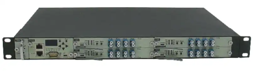
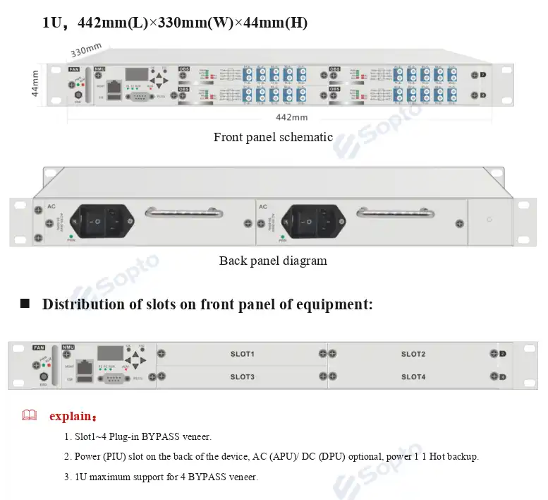
Design with 1U standard 19-inch frame plug-in card structure, single box provides 4 function module slots, 2 power slots and 1 fan slot; use front panel outlet mode, all optical interface and network management interface are designed on the front; air duct design adopts right air inlet and left air outlet, air inlet is designed on the right side of chassis, cold air is absorbed to inside chassis through cooling fan unit, and then exported from left air outlet of chassis.
Specification and dimension: 1U, 442mm(L)x330mm(W)x44mm(H)
Front Panel Slot Distribution
- Slot 1~4: Plug-in BYPASS veneer
- Power (PIU) slot: On the back of the device, AC (APU)/DC (DPU) optional, power 1+1 hot backup
- 1U maximum support: 4 BYPASS veneers
V. NMU Net Element Control Processing Board
NMU is a network management function module specially designed for OSP2800 series of products. The main function is to provide the interface between the equipment and the network management system together with OSP2800 series of network management systems, the single board management, all kinds of maintenance and management signal transmission of the network elements are completed.
Product Characteristics
- Provides a RJ45 Ethernet interface to support graphical SNMP network management based on IP
- Provides a Console interface to support simulation terminal operation
- HD Dual Color LCD Display
- Six keystrokes and concise
Product Description
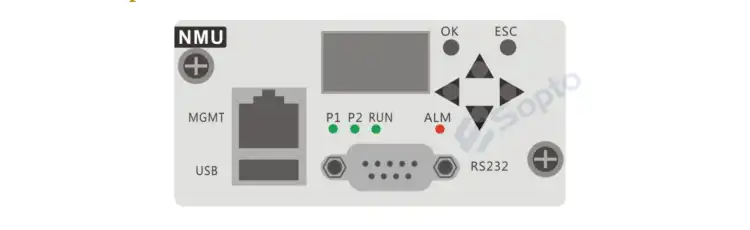
- OLED display screen: Display of relevant information such as current status, IP address, device instruction address etc.
-
Pilot lamp:
- P1/P2: Indicates the current power supply working state, the light indicates the power supply is working, the light out indicates that the power supply is not working
- RUN: Running lights
- ALM: Indicates the current alarm state of the device link, the red light indicates that there is an alarm in the link, and the light out indicates that all links are normal
-
Key-press:
- OK: Enter menu operation, confirm settings
- ESC: Exit menu
- ▲▼◀▶: Move the menu or move the cursor
- RJ45 Ethernet interface: Equipment monitoring data information communication interface, using EIA/TIA 568B standard network terminal connection computer
- RS-232 serial port, USB port: The communication interface of the equipment monitoring data information, the serial port uses the cross serial port line to connect the COM port of the computer, USB uses the USB-A data line to connect the computer port, the driving chip is the PL2303
VI. OBS Light Bypass Protection Card
OBS Card Specification
| Item | Parameter | |
|---|---|---|
| Working wavelength range | 850nm, 1260nm~1650nm | |
| OBP type | OBPA (dual fiber 1+1 protection) | OBPB (dual fiber 1:1 protection) |
| Switching time | <20ms | <20ms |
| Insertion loss - Cascade | <3.5dB (typical 50%:50% splitter) | <1.5dB |
| Insertion loss - Bypass | <4.5dB (typical 50%:50% splitter) | <1.5dB |
| Monitoring power range | -50dBm~+25dBm | |
| Working temperature range | -10°C~60°C | |
| Working humidity range | 5%~95% no condensation | |
| Storage temperature | -40°C~85°C | |
| Optical interface | LC/UPC | |
| Typical power consumption | Full configuration <25W | |
| MTBF | >100000 hours | |
Indicator Light Description
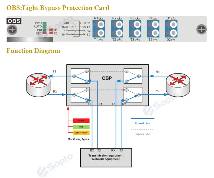
- PWR: Indicates the current power supply working state, the light indicates the power supply is working, the light out indicates that the power supply is not working
- AUTO: Indicating the current operating mode of the device link, the light indicates that the device is in automatic mode, and the light out indicates that it is in manual mode
- PRI: Indicates the current optical path state of the device link, and the green light is the main (online) state
- SEC: Indicates the current optical path state of the device link, and the red light is a standby (off-line) state
- R1/R2: Indicates the R1/R2 optical power state of the link, the red light represents that the optical power is lower than the set threshold value, and the red light extinction represents that the optical power is higher than the set threshold value
Optical Connection Description
The main path schematic diagram and optical path schematic diagram show that R1, R2 input light has optical power monitoring function.
Note: If you need more customized services, please contact us
Email: info@sopto.com.cn
Website: http://www.sopto.com.cn