1. Product Overview
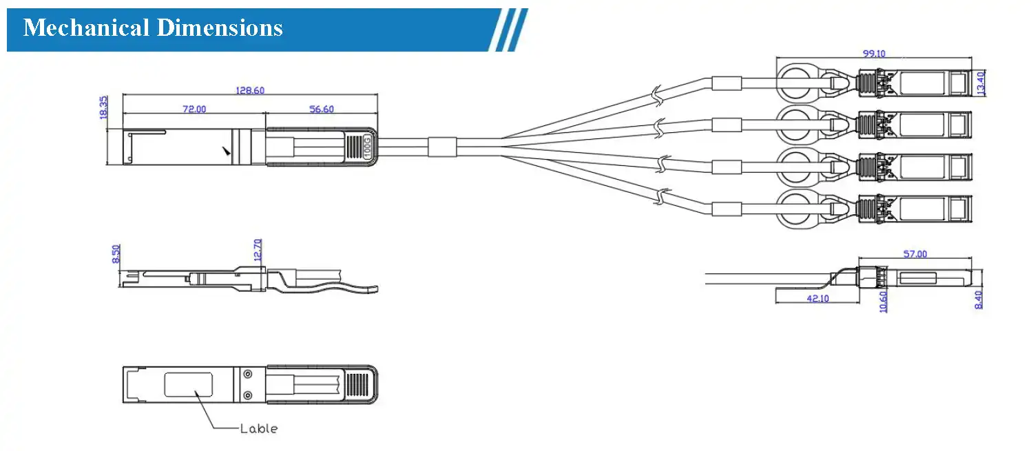
The SPH-Q-4SFP28-C3-30 is a 100G QSFP28 to 4x 25G SFP28 Passive Direct Attach Copper Cable offered by SOPTO, designed for very short-distance high-speed interconnection between QSFP28 and SFP28 devices. This cable provides a cost-effective way to implement 100G link connections while meeting the transmission requirements of 100GbE Ethernet and InfiniBand standards.
The product features QSFP28 38-pin and 4x SFP28 20-pin connectors, AWG30 wire gauge, 3-meter length, and an operating temperature range of 0~70°C. The copper cable supports an aggregate data bandwidth of up to 100Gb/s (4x25Gb/s) and complies with industry specifications including QSFP28 MSA, SFP28 MSA, SFF-8402, SFF-8665, and IEEE 802.3bj 100GBASE-CR4, specifically designed for high-density cabling interconnection in data center and high-performance computing environments.
100Gb/s
aggregate bandwidth
25.78Gb/s
per-channel data rate
3m
cable length
AWG30
wire gauge
+3.3V
power supply
2. Key Features
- 100Gbps to 4x25Gbps rate breakout: One QSFP28 interface splits into four SFP28 interfaces, with a per-channel data rate of 25.78Gb/s and a maximum aggregate data rate of 100Gb/s.
- High-density connector design: QSFP28 38-pin and SFP28 20-pin connectors meet the high-density cabling requirements of data centers.
- I2C two-wire serial interface: EEPROM signature interface based on I2C, supporting custom programming.
- Low crosstalk design: Optimized cable structure effectively reduces inter-channel crosstalk.
- Metal enclosure: Metal enclosure packaging reduces EMI electromagnetic interference.
- Commercial temperature range: 0~70°C operating temperature, suitable for data center room environments.
- Cable length up to 5m: This model is 3m, meeting intra-cabinet and adjacent cabinet interconnection needs.
- RoHS-6 compliant: Compliant with RoHS-6 lead-free standard.
3. Absolute Maximum Ratings
| Parameter | Symbol | Min | Typ | Max | Unit |
|---|---|---|---|---|---|
| Storage temperature | TSTG | -40 | — | +85 | °C |
| Operating temperature | Top | 0 | — | 70 | °C |
| 3.3V supply voltage | VCC | -0.5 | — | +3.6 | V |
| Relative humidity | RH | 0 | — | 85 | % |
| Power dissipation | PD | — | — | 0.1 | W |
4. Electrical Characteristics
| Parameter | Min | Typ | Max | Unit |
|---|---|---|---|---|
| characteristic impedance | 90 | 100 | 110 | Ω |
| time delay | — | — | 4.5 | ns/m |
| time delay skew (within the same differential pair) | — | — | 10 | ps |
| time delay skew (between differential pairs) | — | — | 50 | ps |
5. High Speed Characteristics
| Parameter | Symbol | Min | Typ | Max | Unit | Notes |
|---|---|---|---|---|---|---|
| differential impedance | RIN,P-P | 90 | 100 | 110 | Ω | — |
| insertion loss | SDD21 | 8 | — | 22.48 | dB | At 12.8906GHz |
| differential return loss | SDD11 / SDD22 | 12.45 | — | See Note 1 | dB | At 0.05 to 4.1GHz |
| 3.12 | — | See Note 2 | dB | At 4.1 to 19GHz | ||
| common-mode to common-mode output return loss | SCC11 / SCC22 | 2 | — | — | dB | At 0.2 to 19GHz |
| differential to common-mode return loss | SCD11 / SCD22 | 12 | — | See Note 3 | dB | At 0.01 to 12.89GHz |
| 10.58 | — | See Note 4 | dB | At 12.89 to 19GHz | ||
| differential to common-mode conversion loss | SCD21-IL | 10 | — | See Note 5 | dB | At 0.01 to 12.89GHz |
| 6.3 | — | — | dB | At 15.7 to 19GHz | ||
| channel operating margin | COM | 3 | — | — | dB | — |
High Speed Characteristics Notes
- [1] Reflection coefficient equation: SDD11(dB) < 16.5 - 2×SQRT(f), f in GHz
- [2] Reflection coefficient equation: SDD11(dB) < 10.66 - 14×log10(f/5.5), f in GHz
- [3] Reflection coefficient equation: SCD11(dB) < 22 - (20/25.78)×f, f in GHz
- [4] Reflection coefficient equation: SCD11(dB) < 15 - (6/25.78)×f, f in GHz
- [5] Reflection coefficient equation: SCD21(dB) < 27 - (29/22)×f, f in GHz
6. Compliance
| Specification | Description |
|---|---|
| SFP28 MSA | Compatible with SFP28 Multi-Source Agreement |
| QSFP28 MSA | Compatible with QSFP28 Multi-Source Agreement |
| SFF-8402 | Compatible with SFF-8402 standard |
| SFF-8665 | Compatible with SFF-8665 standard |
| IEEE 802.3bj | Compliant with 100GBASE-CR4 specification |
| IEEE P802.3by | Compliant with P802.3by specification |
| RoHS-6 | Compliant with RoHS-6 lead-free standard |
7. Applications
- 100/25G Ethernet: Data center 100GbE and 25GbE network interconnection.
- Data communication/telecom switches and router connections: High-speed short-distance interconnection between network devices.
- High-speed multi-channel parallel data links: Parallel data transmission between servers and storage devices.
- High-performance computing, servers, and data storage: High-bandwidth interconnection between HPC cluster nodes.
8. Pin Assignment
QSFP28 38-pin Connector Pin Assignment
| Pin | Symbol | Name/Description | Notes |
|---|---|---|---|
| 1 | GND | Ground | [1] |
| 2 | Tx2n | Transmitter Inverted Data Input | — |
| 3 | Tx2p | Transmitter Non-Inverted Data Input | — |
| 4 | GND | Ground | [1] |
| 5 | Tx4n | Transmitter Inverted Data Input | — |
| 6 | Tx4p | Transmitter Non-Inverted Data Input | — |
| 7 | GND | Ground | [1] |
| 8 | ModSelL | Module Select | — |
| 9 | ResetL | Module Reset | — |
| 10 | VccRx | +3.3V receiver power supply | [2] |
| 11 | SCL | Two-wire serial interface clock | — |
| 12 | SDA | Two-wire serial interface data | — |
| 13 | GND | Ground | [1] |
| 14 | Rx3p | Receiver Non-Inverted Data Output | — |
| 15 | Rx3n | Receiver Inverted Data Output | — |
| 16 | GND | Ground | [1] |
| 17 | Rx1p | Receiver Non-Inverted Data Output | — |
| 18 | Rx1n | Receiver Inverted Data Output | — |
| 19 | GND | Ground | [1] |
| 20 | GND | Ground | [1] |
| 21 | Rx2n | Receiver Inverted Data Output | — |
| 22 | Rx2p | Receiver Non-Inverted Data Output | — |
| 23 | GND | Ground | [1] |
| 24 | Rx4n | Receiver Inverted Data Output | — |
| 25 | Rx4p | Receiver Non-Inverted Data Output | — |
| 26 | GND | Ground | [1] |
| 27 | ModPrsL | Module Present | — |
| 28 | IntL | Interrupt | — |
| 29 | VccTx | +3.3V transmitter power supply | [2] |
| 30 | Vcc1 | +3.3V power supply | [2] |
| 31 | LPMode | Low Power Mode | — |
| 32 | GND | Ground | [1] |
| 33 | Tx3p | Transmitter Non-Inverted Data Input | — |
| 34 | Tx3n | Transmitter Inverted Data Input | — |
| 35 | GND | Ground | [1] |
| 36 | Tx1p | Transmitter Non-Inverted Data Input | — |
| 37 | Tx1n | Transmitter Inverted Data Input | — |
| 38 | GND | Ground | [1] |
- [1] GND is the common ground for signals and power. All ground pins inside the QSFP28 module are shared and connected directly to the host board signal common ground plane.
- [2] VccRx, Vcc1, and VccTx are the receiver and transmitter power supplies and must be powered on simultaneously. Maximum current per connector pin is 500mA.
SFP28 20-pin Connector Pin Assignment
| Pin | Symbol | Name/Description | Notes |
|---|---|---|---|
| 1 | VEET | Transmitter ground (shared with receiver ground) | — |
| 2 | TFAULT | Transmitter fault indication | [1] |
| 3 | TDIS | Transmitter Disable. Laser output disabled when high or open | [2] |
| 4 | SDA | Two-wire serial interface data line | — |
| 5 | SCL | Two-wire serial interface clock line | — |
| 6 | MOD_ABS | Module present detection. Internally grounded in the module | — |
| 7 | RS0 | No connection required | [1] |
| 8 | RX_LOS | Loss of Signal indication. Logic 0 indicates normal operation | [2] |
| 9 | RSI | No connection required | [1] |
| 10 | VEER | Receiver ground (shared with transmitter ground) | — |
| 11 | VEER | Receiver ground (shared with transmitter ground) | — |
| 12 | RD- | Receiver Inverted Data Output, AC coupled | — |
| 13 | RD+ | Receiver Non-Inverted Data Output, AC coupled | — |
| 14 | VEER | Receiver ground (shared with transmitter ground) | — |
| 15 | VCCR | Receiver power supply 3.3V | — |
| 16 | VCCT | Transmitter power supply 3.3V | — |
| 17 | VEET | Transmitter ground (shared with receiver ground) | — |
| 18 | TD+ | Transmitter Non-Inverted Data Input, AC coupled | — |
| 19 | TD- | Transmitter Inverted Data Input, AC coupled | — |
| 20 | VEET | Transmitter ground (shared with transmitter ground) | — |
- [1] This signal is not supported in SFP28 copper cables and is pulled down to VeeT through a 30kΩ resistor.
- [2] LOS and TX_DIS functions are not supported in passive copper cable assemblies.
9. Ordering Information
| Part Number | Product Description |
|---|---|
| SPH-Q/4SFP28-C3-30 | High-speed copper cable Passive Direct Attach Copper Cable 100G QSFP28 to 4SFP28 3m AWG30 PVC commercial temperature |
For customized services, please contact SOPTO via the following:
Email: info@s-opto.com
Website: www.s-opto.com
10. Glossary
| Abbreviation | Full Name | Definition |
|---|---|---|
| QSFP28 | Quad Small Form-factor Pluggable 28 | Quad-channel small form-factor pluggable package, supporting 25Gb/s per channel with a total bandwidth of 100Gb/s. |
| SFP28 | Small Form-factor Pluggable 28 | Small form-factor pluggable package, supporting 25Gb/s data rate. |
| DAC | Direct Attach Copper | Direct attach copper cable, used for short-distance high-speed interconnection between devices. |
| MSA | Multi-Source Agreement | A product interface standard jointly developed by multiple manufacturers. |
| AWG | American Wire Gauge | American wire gauge standard; the larger the number, the thinner the wire. AWG30 corresponds to a relatively thin wire diameter. |
| 100GBASE-CR4 | 100 Gigabit Baseband - CR4 | A 100Gb/s four-channel copper cable interconnection standard defined by IEEE 802.3bj. |
| InfiniBand | InfiniBand | A serial interconnection standard for high-performance computing, supporting high bandwidth and low latency. |
| I2C | Inter-Integrated Circuit | A two-wire serial communication protocol used for module EEPROM read/write and identification. |
| EMI | Electromagnetic Interference | Electromagnetic interference; the metal enclosure design reduces external radiation. |