Practical Guide to Fiber Optic Communication Fundamentals
This is an engineering-oriented technical tutorial based on ITU-T and TIA industry standards with no fabricated parameters, suitable for foreign trade product blogs, pre-sales technical documentation, and engineering入门 learning.
I. What is Fiber Optic Communication
Fiber optic communication is a communication method that uses light waves as carriers and quartz optical fiber as the transmission medium, modulating electrical signals onto light pulses for long-distance data transmission.
Simple link logic:
Electrical signal → Optical transmitter module (E/O conversion) → Fiber transmission → Optical receiver module (O/E conversion) → Restored electrical signal.
Core advantages compared to copper cables:
- Electromagnetic interference resistant, stable signal in frequency converters and industrial high-voltage environments;
- Extremely large bandwidth, a single fiber can carry TB-level traffic;
- Low transmission loss, single-mode fiber at 1550nm window is about 0.2dB/km, long distance without frequent repeaters;
- Lightweight, small size, signal not easy to eavesdrop;
Shortcomings: Glass fiber is fragile, bending radius has hard limits, end faces are extremely susceptible to dust contamination, splicing and termination require specialized precision tools.
II. Fiber Classification and ITU Standards (Core for Engineering Selection)
Optical fiber consists of three layers: core (light transmission), cladding (light confinement, lower refractive index than core), coating (mechanical protection), relying on total internal reflection to confine light signals within the core.
1. Single-Mode Fiber (SMF)
Core diameter 8~10μm, allows only one light mode to propagate, no intermodal dispersion, suitable for long distances.
- G.652D: Most universal, mainstream for metropolitan networks, FTTH, equipment patch cords in China, 1310nm/1550nm dual window;
- G.654: Ultra-low loss, submarine cables;
- G.655: Non-zero dispersion shifted fiber, DWDM long-distance backbone;
- G.657: Bend-insensitive fiber, building indoor wiring, allows smaller bending radius.
2. Multi-Mode Fiber (MMF)
Core 50μm / 62.5μm (OM1), multiple light beams transmitted simultaneously, exists intermodal dispersion, short distance, mostly used for server rooms and data center short-distance wiring.
- OM1: 62.5/125, old server rooms;
- OM3/OM4: 50/125, VCSEL light source, 10G, 25G data centers;
Selection rule: Long distance, cross-city, backbone network choose single-mode G.652; short-distance interconnection within hundreds of meters in server rooms choose multi-mode OM3/OM4.
III. Core Components of Fiber Optic Communication (Active + Passive)
Active Components (Require power, complete optoelectronic conversion / amplification)
- Optical Transceiver
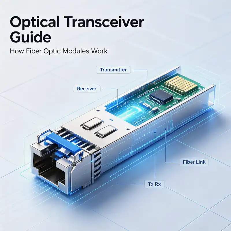
The most core component in the industry, integrates TOSA transmitter assembly, ROSA receiver assembly, DSP signal processing chip.
TOSA: Laser, electrical to optical; ROSA: Photodetector, optical back to electrical. Models such as SFP, SFP+, QSFP28, universal for switches and server network ports. - EDFA (Erbium-Doped Fiber Amplifier)
1550nm band, directly amplifies optical signals without optoelectronic regeneration, essential for long-distance DWDM systems.
Note: Can only amplify optical power, cannot repair signal distortion caused by dispersion.
Passive Components (No power required, optical path physical processing)
- Fiber connectors: SC/LC/FC/ST, equipment and patch cord termination, end faces are high-failure points;
- Splice Closure: Outdoor overhead / duct, protects fiber splicing points;
- Optical splitter: PON network splitting, 1 to 4, 1 to 8, 1 to 16;
- WDM (Wavelength Division Multiplexer): Multiple different wavelength lights merged into one fiber, increasing fiber capacity.
IV. Fiber Engineering Practice: Splicing, End-Face Inspection and Testing
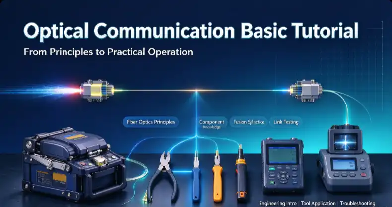
This part is the most commonly used content in field construction, corresponding to products: fusion splicer, thermal stripper, handheld end-face probe, OTDR, optical power meter.
1. Fusion Splice Process
- Pre-treatment: Cable stripping, insert heat shrink protection sleeve;
- Stripping: Use fiber stripper to remove 250μm acrylic coating, bare fiber length 2~5cm;
Thermal stripper is used for difficult-to-strip tight-buffered fiber, relies on high temperature to melt coating, avoiding glass core scratches;
- Cleaning: 99.7% anhydrous alcohol + lint-free paper unidirectional wiping of bare fiber, oil and dust directly bring high loss;
- Cleaving: Fiber cleaver prepares end face, end face angle must be <1°, mirror surface flat, chipping and gaps directly scrap;
- Splicing: Place into splicer V-groove, machine automatically aligns and discharges to melt. Single-mode splicing estimated loss target ≤0.05dB;
- Heat protection: Center the splice point into heat shrink tube and heat to cure;
- Testing: Splicer screen estimated value is only for reference, must use OTDR bidirectional testing for real loss, unqualified must re-splice.
2. End-Face Inspection
Fiber end face dust and scratches are the most common link failure sources. Use handheld end-face probe (fiber microscope) to magnify and observe the end face, dirty end faces will cause reflection, excessive insertion loss, leading to optical transceiver bit errors and packet loss.
Maintenance common sense: Dirty end face, prioritize using fiber cleaning pen, prohibit directly wiping with tissue paper or clothes.
3. Link Testing Tools
- Optical power meter: Measures link received optical power, quickly determines optical path connectivity, whether power is within module receiving sensitivity range;
- OTDR (Optical Time Domain Reflectometer): Curve locates breakpoints, splice point loss, fiber bending damage, can measure every loss point position along the entire cable, troubleshooting artifact.
V. Two Core Damage Factors of Fiber: Loss and Dispersion
- Loss (Attenuation, unit dB)
Optical power decreases during fiber transmission, three sources: absorption loss, Rayleigh scattering, bending loss.
Micro-bend / macro-bend is the most easily artificially introduced loss in field construction, wiring must not be less than minimum bending radius, strictly prohibit sharp bends. - Dispersion
Different frequency / mode light travels at inconsistent speeds, pulse broadening, signal deformation. Single-mode fiber is mainly chromatic dispersion; multi-mode is mainly intermodal dispersion, limiting transmission distance.
VI. Common Engineering Troubleshooting (Practical)
- Link not working / high packet loss
Priority troubleshooting: Fiber end face dirty → Splice point loss exceeds standard → Fiber squeezed and bent → Optical transceiver mismatch (single/multi-mode mixed use, wavelength mismatch).
High-frequency pitfall: G.652 single-mode fiber cannot be directly paired with OM multi-mode optical transceiver, forced use will completely fail to communicate.
- Optical power fluctuates high and low
Most likely: Connector loose, end face contamination, cable squeezed by external force. - Splice loss too large
Common causes: Fiber model mismatch, poor end face cleaving, inadequate bare fiber cleaning, splicer V-groove / electrode dust accumulation.
VII. Application Scenarios
- Backbone / Metropolitan network: Long-distance fiber, DWDM+EDFA;
- FTTx broadband to home: G.657 bend-insensitive fiber, optical splitter;
- Industrial Ethernet: Industrial switch + PoE + fiber, anti-interference;
- Data center: OM3/OM4 multi-mode short-distance interconnection;
- Security monitoring: Long-distance camera transmission, replacing network cables.
VIII. Safety Precautions
- Do not look directly at bare fiber end face with naked eye: Laser invisible infrared light will damage retina;
- Glass debris after stripping is extremely fine, avoid skin penetration, collect and dispose properly;
- Fiber cable construction strictly prohibits strong pulling, fiber has maximum tensile threshold.
Contact Us
Email: info@sopto.com.cn
Website: http://www.sopto.com.cn